![]()
Part 1 Principles
1. Fluorescence microscope
2. Filterset
in FL-Mic
3. How concocal differs?
4.
What is confocal?
5.
Resolution in confocal
6. Optical
sectioning
7. Confocal image formation
and
time resolution
8. SNR in
confocal
9.
Variations of confocal
microscope
10. Special features from
Leica sp2 confocal
![]()
Part 2
Application
1. Introduction
2.
Tomographic view
(Microscopical CT)
3. Three-D reconstruction
4. Thick specimen
5. Physiological study
6.
Fluorescence detecting
General
consideration
Multi-channel detecting
Background correction
Cross-talk correction
Cross excitation
Cross emission
Unwanted FRET
![]()
Part
3 Operation and
Optimization
1.
Getting started
2. Settings in detail
Laser line
selection
Laser intensity and
AOTF control
Beam
splitter
PMT gain and offset
Scan
speed
Scan format, Zoom
and Resolution
Frame average, and
Frame accumulation
Pinhole and Z-resolution
Emission collecting rang
and Sequential scan
![]()
When Do
you need confocal?
FAQ
Are
you abusing
confocal?
Confocal Microscopy tutorial
Part 1 Principles of Confocal microscopy
![]()
2. Filter-set and its choice, limitation
A detailed internal structure of the filter-set cube containing above-mentioned filter 5, 8, 9, shown here as A, B, C and its light path is given below:
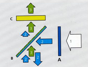
Arrow 1 represents the excitation light source of mixed wavelength.
Filter
A is the excitation filter, which is usually a band pass or long
pass filter, allows light at certain wavelength range or wavelength longer
than cut-off value to go through. For a filter cube designed
for simultaneous multiple fluorescence detecting, a long pass filter with
cut-off value shorter than the shortest excitation has to be used. That
leads more unwanted wavelength to specimen results in more nonspecific
background fluorescence.
Arrow 2 represents excitation light which passes through A and reaches the surface of Beam Splitter B, BSP is a special filter which reflects certain wavelength away but permit other wavelength to pass. A multiple-bands reflecting filter or neutral percentage splitter can be used for this role. Wavelength falling into the reflecting band or shorter than the cut-off value will be stopped and reflected to the specimen. The fluorescence light emitted from specimen is illustrated as Arrow 3. The emission is longer than excitation wavelength and cut-off value of the BSP, so the returned emission can go through the BSP towards emission filter C.
Unfortunately, these two tasks placed on the single filter are
contradictory. Reflecting certain wavelength to specimen for excitation means
blocking it from transmission.
Beam splitter is not a magician, it can not distinguish which is excitation
and which is emission light. It simply reflects certain band of wavelength
towards specimen even if it is the emission coming back from specimen. In
single fluorophore labeling, there is no problem. But in scenario of double or
multiple labeling, if the shorter emission extends to the wavelength area of the
next longer
excitation, this part of emission will lost on the way back
to detector, all the later fluorophores will suffer some loss. This is known as "emission hole".
The more bands a BSP has, the more barrier zones it contains. So, don't use multi-band chroic
unless necessary. For details on how to choose BSP, refer part 3, Operation and
optimization: Beam Splitter.
Emission filter C. Emission filter is either a band pass filter or long pass filter, the cut-off value is longer than excitation wavelength so the residue of excitation light 2 is further prevented from reaching image plane. Strict band pass results more specific but weaker signal, while long pass leads stronger signal but more background.
![]()
Statement about this web and
tutorial
For problems or questions regarding this web contact
e-mail:
This page was last updated
23.03.2004