![]()
Part 1 Principles
1. Fluorescence microscope
2. Filterset
in FL-Mic
3. How concocal differs?
4.
What is confocal?
5.
Resolution in confocal
6. Optical
sectioning
7. Confocal image formation
and
time resolution
8. SNR in
confocal
9.
Variations of confocal
microscope
10. Special features from
Leica sp2 confocal
![]()
Part 2
Application
1. Introduction
2.
Tomographic view
(Microscopical CT)
3. Three-D reconstruction
4. Thick specimen
5. Physiological study
6.
Fluorescence detecting
General
consideration
Multi-channel detecting
Background correction
Cross-talk correction
Cross excitation
Cross emission
Unwanted FRET
![]()
Part
3 Operation and
Optimization
1.
Getting started
2. Settings in detail
Laser line
selection
Laser intensity and
AOTF control
Beam
splitter
PMT gain and offset
Scan
speed
Scan format, Zoom
and Resolution
Frame average, and
Frame accumulation
Pinhole and Z-resolution
Emission collecting rang
and Sequential scan
![]()
When Do
you need confocal?
FAQ
Are
you abusing
confocal?
Confocal Microscopy tutorial
Part 3 operation, optimization of Leica SP2 LSCM
![]()
Pinhole, resolution and optical section thickness
As emphasized in
Part 1 section 5, pinhole is
the main player of confocal effects. Through its out-of-focal-plane signal
rejection, optical sectioning is possible. When pinhole is indefinite small or
in practical, smaller than 0.25 AU; the thickness of optical section is
not influenced by pinhole size any more but solely decided by axial resolution
of objective lens in use, reach the thinnest level:
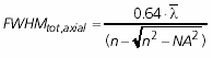 ,
,
the lateral resolution also reaches smallest to
![]() ,
about 1.4 times over conventional optical system.
,
about 1.4 times over conventional optical system.
But when pinhole is smaller than 0.25 AU, because of
the additional diffraction and greatly reduced signal intensity and the
deteriorated SNR, all these resolution gain are lost in the noisy image. Pinhole
size between 0.25 and 1 AU is the usual working range. At this range, for
lateral resolution, coefficient 0.37 has to be substituted by value between 0.37 and 0.51 depending
on the actual pinhole size in use. The optical section is
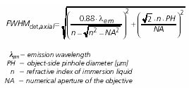 thicker
than the z-resolution of the objective and is determined by the actual pinhole
size in use.
thicker
than the z-resolution of the objective and is determined by the actual pinhole
size in use.
So, in practical, pinhole size is mainly used to control optical section
thickness other than to achieve highest lateral or Z-resolution.
The calculation of optical section thickness is not convenience by using this
formula because the physical size of pinhole in use has to be known or deduced
from the AU in use. Generally speaking, the z-resolution is about 2 times of
the lateral resolution. Ref table 2 for
resolution of objectives equipped in this microscope.
In Leica LCS software, under Hardware legend, an
entry "Voxel-size" can be seen. The last value represent the
sampled section thickness. But this value is simply the quotient of the z-dimension of
the image (derived from the starting and ending position of the Z-series)
divided by the number of sections you have set. It is not the actual optical
section thickness.
In the following example, that is:
12.7µm / (40-1)=325 nm.
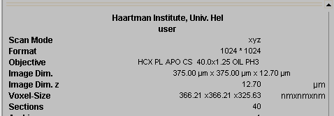
If the value you get here is too small (less than half of the z-resolution of the objective lens you use), the section number you set is unnecessarily too much.
Occasionally, pinhole size can be used to adjust amount of photon received by PMT to change the signal intensity and increase SNR. In addition to the "optimal" 1 AU, Pinhole 1-3 AU is the range of choice. Bigger pinhole give you stronger signal but with the compromised confocal effects.
![]()
Statement about this web and
tutorial.
For problems or questions regarding this web contact
e-mail:
This page was last updated 23.03.2004