![]()
Part 1 Principles
1. Fluorescence microscope
2. Filterset
in FL-Mic
3. How concocal differs?
4.
What is confocal?
5.
Resolution in confocal
6. Optical
sectioning
7. Confocal image formation
and
time resolution
8. SNR in
confocal
9.
Variations of confocal
microscope
10. Special features from
Leica sp2 confocal
![]()
Part 2
Application
1. Introduction
2.
Tomographic view
(Microscopical CT)
3. Three-D reconstruction
4. Thick specimen
5. Physiological study
6.
Fluorescence detecting
General
consideration
Multi-channel detecting
Background correction
Cross-talk correction
Cross excitation
Cross emission
Unwanted FRET
![]()
Part
3 Operation and
Optimization
1.
Getting started
2. Settings in detail
Laser line
selection
Laser intensity and
AOTF control
Beam
splitter
PMT gain and offset
Scan
speed
Scan format, Zoom
and Resolution
Frame average, and
Frame accumulation
Pinhole and Z-resolution
Emission collecting rang
and Sequential scan
![]()
When Do
you need confocal?
FAQ
Are
you abusing
confocal?
Confocal Microscopy tutorial
Part 1 Principles of Confocal microscopy
![]()
10. Special features from Leica SP2 confocal microscope
-
Emission-filter free spectral detecting system
Leica SP2 confocal microscope has two unique hardware innovations. The first one is the emission filter free spectral meter detecting system, introduced in 1999, depicted as below:
 |
 |
Like in picture on the left, the emission is first spread by prism into spectra, this spectra is further selected by a motor-driven slit which can change width or move position laterally as in picture on the right. With this device, the detecting wavelength, detecting band width can be continuously changed within 400 -750 nm to meet emission from any fluorophores without need of add new filter set into the system. a lambda scan within the whole range enable you to determine where is the emission peak of your stain and further optimizing of detecting position and range has more accurate basis.
-
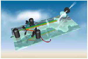
Beamsplitter-free AOBS system
The beam-splitting-filter free AOBS (acousto optical beam splitter) system is introduce in 2002.
 |
 |
Here the ordinary BSP is replaced by a optical crystal with an ultrasonic field applied. The wavelength and amplitude of the ultrasound can be changed (programmed) to deflect certain band of wavelength and its amount passing through the field (figure on the left). Up to eight excitation bands can be programmed at the same time compared to only three bands in tri-chroic BSP in ordinary filter based system. Besides, the band width of the deflected is very narrow or sharp, around 1 nm only (0.6 - 3 nm proportional to the wavelength concerned), compared to ordinary BSP which has about 10 to 20 nm width of barrier to emission know as "emission hole" (figure on the right).
In short, this function has two major benefits: 1. removal of the limitation on the number of beam splitter available in the system and more accurate control on the reflected bands. 2. Higher efficiency for emission collection.
These two approaches: AOBS and spectra detecting create totally filter-free confocal microscope which provides more versatility and higher efficiency in choosing excitation and collecting emission.
![]()
Statement about this web and tutorial
For problems or questions regarding this web contact
e-mail:
This page was last updated
23.03.2004