![]()
Part 1 Principles
1. Fluorescence microscope
2. Filterset
in FL-Mic
3. How concocal differs?
4.
What is confocal?
5.
Resolution in confocal
6. Optical
sectioning
7. Confocal image formation
and
time resolution
8. SNR in
confocal
9.
Variations of confocal
microscope
10. Special features from
Leica sp2 confocal
![]()
Part 2
Application
1. Introduction
2.
Tomographic view
(Microscopical CT)
3. Three-D reconstruction
4. Thick specimen
5. Physiological study
6.
Fluorescence detecting
General
consideration
Multi-channel detecting
Background correction
Cross-talk correction
Cross excitation
Cross emission
Unwanted FRET
![]()
Part
3 Operation and
Optimization
1.
Getting started
2. Settings in detail
Laser line
selection
Laser intensity and
AOTF control
Beam
splitter
PMT gain and offset
Scan
speed
Scan format, Zoom
and Resolution
Frame average, and
Frame accumulation
Pinhole and Z-resolution
Emission collecting rang
and Sequential scan
![]()
When Do
you need confocal?
FAQ
Are
you abusing
confocal?
Confocal Microscopy tutorial
Part 1 Principles of Confocal microscopy
![]()
7. Image Generation in confocal microscopy
In conventional microscopy, the image formation is instantaneously. The photographic film or CCD chip in a camera or the retina in human eyes, detect the whole image from the exit of the microscope immediately.
While in confocal microscope, the illumination light is directed (scanned) onto the specimen dot by dot through a mirror on galvon-motor-driven scanner. The emitted light from specimen is collected and de-scanned dot by dot then passes through detecting pinhole and reaches photo multiplier tube (PMT). So, both illumination and image detection depend on the scanning process, i.e. the image is generated through scanning. Understanding this is helpful for new users in their struggle to get their first image. A frequent question from new user is "I need an image, but why there is constant scanning ?!".
PMT has large active area compared to the small cell on a CCD chip, thus can accommodate more electron and has wide dynamic range (range between maximum and minimum detectable intensity). PMT has high photon sensitivity suitable for detecting both strong and weak signal, providing there is enough SNR. Since there is no charge accumulation as on a CCD chip, PMT has very quick refresh rate and can detect single photon in nano second level.
 PMT detects
light and converts photon
hits into analogue electron flow. The
continuous analogue electron signal is then
sampled at separate time point, digitized into discrete
digital signal by Analogue to Digital converter (ADC),
then
processed by image processor, dot by
dot into a line, and line by line into a frame, the image is reconstructed in
the image memory and drawn on the screen.
PMT detects
light and converts photon
hits into analogue electron flow. The
continuous analogue electron signal is then
sampled at separate time point, digitized into discrete
digital signal by Analogue to Digital converter (ADC),
then
processed by image processor, dot by
dot into a line, and line by line into a frame, the image is reconstructed in
the image memory and drawn on the screen.
Although PMT detects photon very fast, but an image frame consists many dots and lines. The speed for confocal microscope to form an image frame is limited by the line frequency of the scanner. With a 1k Hz frequency (1 ms per line), one second is needed to form a frame with1000 lines. If more than one frame are needed such as in time laps acquisition, the frame rate is further limited by the time needed to scan all the lines in a frame, plus the time needed to re-position the scanner to the starting point again. The frame rate is rather slow in confocal system for frames containing lot of lines, with commonly used scanner speed at 400 Hz, the frame rate is about 0.4 FPS (frame per second) for a 1024 x 1024 frame. Even with 1000 Hz speed, frame rate is still less than 1 FPS.
Since PMT is not limited by a matrix of photo detecting cell array like in a CCD chip, there is more freedom to get more pixels in a frame by simply sampling more pixels along a line and scan more lines over longer period of time. Thus, a 4096 pixel x 4096 lines format can be used to get a very high resolution frame. It is worth noting that the total time is the function of the number of lines needed and frequency of the scanner. Pixel per line does not consume extra time of scanning, the pixel number sampled along a single line is determined by sampling frequency of the ADC and memory avaible for the ADC in the scanhead. But for high scan speed at 1000 and 800 Hz, 4098 sampling is not available since there is not enough time for it.
Generally speaking, in terms of speed, confocal microscopy is slower than CCD camera based system in the frame based acquisition. But the line frequency can be used more "economically" in confocal in line scan mode where no matrix of "m x n" is needed. Normal scanner can reach 1000 Hz refresh rate, and 2000 Hz if bi-direction scan is used. A resonant scanner in bi-direction scan reaches 8000 Hz refresh rate. While the fastest CCD camera reaches only 500 frame per second even under high 32 x binning, for which a small frame of 20 x 15 pixel still has to be acquired.
High line frequency and multi-channel detection with no time delay are advantages of laser scanning confocal system. If capture highly dynamic process is more important than capture high quality image frame, confocal is preferred in these time-sensitive, multi-channel application.
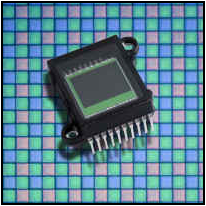
 In CCD camera, CCD
chip itself is insensitive to color. Color CCD camera uses filters to
separate color light to certain area on CCD chip or to different CCD chips in
3-CCD system.
In CCD camera, CCD
chip itself is insensitive to color. Color CCD camera uses filters to
separate color light to certain area on CCD chip or to different CCD chips in
3-CCD system.
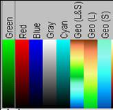
PMT in confocal microscope is also color insensitive and there are no matrix of cells to
receive different color information. Instead, look up table (LUT) is used to
assign different color to signals collected from different PMTs.
As discussed above, image formation process involves dot by dot, line by line scan. Scanning is an important step in confocal image acquisition: many parameters influence the final results and should be optimized. During image optimization process, up to ten parameters, including laser line selection and AOTF laser control, beam splitter selection, PMT gain and offset adjusting, detecting pinhole size, detecting spectral range, LUT setting for each channel, scan speed, frame format, frame average and zoom factor, have to be set up properly. For details, refer part 3 of this tutorial: Operation and Optimization
![]()
Statement about this web and tutorial
For problems or questions regarding this web contact
e-mail:
This page was last updated
23.03.2004